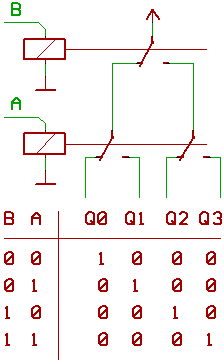
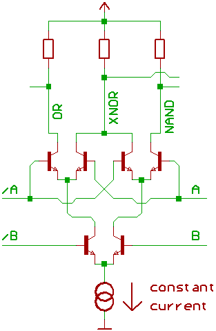
Now for something different: a decoder.
A, B select one output (Q0, Q1, Q2 Q3) to be routed to the supply voltage...
Of course, it doesn't have to be the supply voltage.
It also could be an "enable signal", a little bit like with the 74139.
By the way, it's possible to tie some of the outputs together:
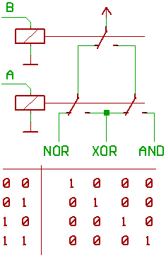
Looks like it's possible to use this in our four relay adder,
so we could save one switch...
maybe for integrating a register (ACC) into the ALU.
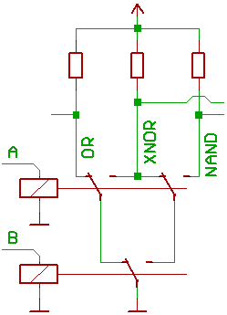
Another idea would be, to use a 4:1 multiplexer which connects
to the adder output, and the logic functions NOR, XOR, AND.
This might take 6 (Two-Pole-Double-Switch) relays per Bit,
and maybe some additional relays for inverting the ALU B input
(for A-B), and for forcing B to 0 or -1 (for incrementing/decrementing A).
There is a more efficient approach, it shows up at the next page...
Another thing is, that we could turn the "pyramid" of relay switches
"upside down", so that it routes one of four inputs to one output.
In other words, we are building a multiplexer,
a little bit like with the 74153.
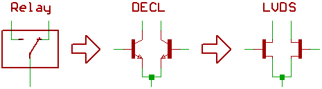
Speaking of switches...
Left to right:
Relay switch from the stone age,
bipolar differential emitter coupled current switch,
differential Current switch with FETs ...as used in Pentium 4.
Of course, when technology changes, design rules also change...
I'm leaving out quite a few details.
...the "automatic Digital Computation symposium 1953"
(available at Bitsavers) gives you a few hints about how to
do such things with vacuum tubes,
take a look at the MOSAIC computer.
Nevertheless:
Taking a look at the "pyramid" of switches while comparing relay
switches with differential transistor pairs leads to interesting results.
[HOME] [UP]/ [BACK] [1] [2] [3] [4] [5] [6] [7] [8] [NEXT]
(c) Dieter Mueller 2008