Now for something more complicated.
Let's imagine, our relays have more switches, and we would
like to use only two Four-Pole-Double-Throw relays instead
of four Two-Pole-Double-Throw relays.
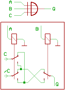
First, we take a look at our three_input XOR gate.
It's kind of obvious, that we are unable to build
a three_input logic gate by using only two relays,
isn't it ?
Nevertheless, there is a trick:
If we happen to have one of the three input signals
in "inverted" and "non inverted" version, it's possible.
In other words, we now use an "inverted"
and a "non inverted" carry signal.
For the high active (non inverted) carry signal, it's simple:
If A = 1 and B = 1 (AND) C_OUT is 1
(tied to supply voltage, that is).
IF A <> B (XOR), C_IN is routed towards C_OUT.
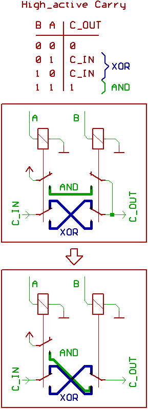
Note the cute trick, how to save one of the switches...
Now for the low active (inverted) carry.
IF A <> B (XOR), /C_IN is routed towards /C_OUT,
we already know this game.
If A = 0 and B = 0 (NOR), /C_OUT is set to inactive,
what means logic 1.
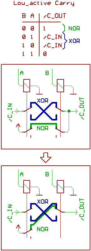
Again, we could save a switch there...
Noticed, that one contact of the switch that ties
the output to 1 is free ?
Now to clobber the whole thing together:
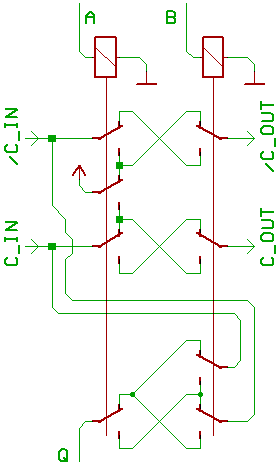
Oops, looks like we have saved another switch.
[HOME] [UP]/ [BACK] [1] [2] [3] [4] [5] [6] [7] [8] [NEXT]
(c) Dieter Mueller 2008