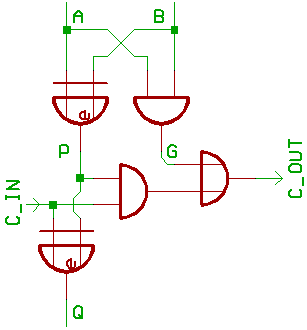
We are starting with the well known one Bit full adder,
which I did mention already in my previous ALU articles...
Just in case you forgot (or you didn't read them):
To make it short, Q = A + B + C_IN.
If A = 1 and B = 1, G = 1 and C_OUT passes the carry to the next higher Bit.
If A = 1 or  B = 1, C_IN from the previous Bit is passed trough to C_OUT.
Besides that, we generate Q with a three_input
XOR logic gate from the input signals A, B, C_IN.
Let's suppose, we are using 74HCT CMOS logic.
Component count for an 8 Bit adder would be:
4* 74HCT86
4* 74HCT08
2* 74HCT32.
Now for a slightly different implementation:
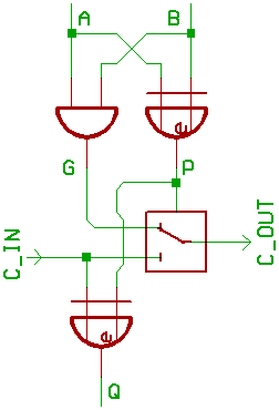
Note the switch.
If A = B, the AND gate is connected to C_OUT.
Means, that if A = 1 and B = 1, C_OUT is 1.
If A = 0 and B = 0, C_IN can't get through.
If A <> B, either A or B is 1.
The switch then routes C_IN to C_OUT.
Component count for 8 Bit:
4* 74HCT86
2* 74HCT08
3* 74HCT4053.
So we need less components than with the previous schematic,
and maybe the signal passes faster trough the switch than
trough an AND/OR gate...
(Take care: when wiring too many such switches in series,
there is a chance that the capacitance of the 74HCT86 inputs
may slow down your signal.)
We might suppose, that CMOS switches are used
inside modern microcontrollers...
(This article was written in 2008.)
Talking of switches, we now try something different:
Two-Pole-Double-Throw Relays.
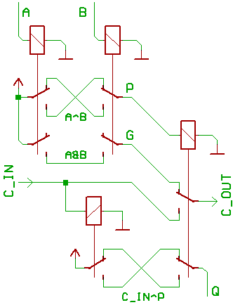
It uses the same concept as our prevous 74HCT based schematic.
A, B control two relays, which emit our AND/XOR signals.
P (propagate) will feed/propagate C_IN trough to C_OUT, if A = 1 or B = 1.
G (generate) is used to generate C_OUT, if A = 1 and B = 1
Again, we use a three_input XOR to generate Q out of A, B, C_IN.
"Neat.", you may say, "but what is the use of turning a modern
design into a boring implementation which uses technology
from the past ?"
Point is, that such relay adders already were in use before ICs, even transisors,
were invented. And if we are digging a bit deeper, maybe by asking an electrician,
we are getting a nice story of how to wire two switches together to control
one light bulb...
of course, it's called "multiway switching" then, instead of "XOR logic gate".
Long time ago, Konrad Zuse did have plenty of trouble with the bureaucrats
from the patent office. Looks like they did not believe in computers and didn't
find the idea of building one worthy for being filed as a patent.
On the bright side, his struggle did create plenty of documentation
about what to do with relays...
[HOME] [UP]/ [BACK] [1] [2] [3] [4] [5] [6] [7] [8] [NEXT]
(c) Dieter Mueller 2008