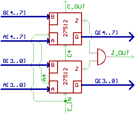
When "only" building a simple 8 Bit CPU,
connecting two EPROMs together like 74181
is the simplest way to go.
However, some care must be taken for shifting Bits,
especially to the right.
The lower EPROM that emits Q3..0 must have
at least one additional Bit at one input_Bus
(A4..0 or B4..0, for instance).
The upper EPROM with Q7..4 requires to be connected
to the Carry input and output from the lower EPROM.
Also note, that we need a logic AND between the
Zero_Flag outputs from both EPROMs.
(ALU_control lines not shown.)
One more word to the C_sourcecode that generates the bitmaps:
While arithmetic and logic operations are programmed
in more or less the same way for both EPROMS,
shift operations will always look different.
Unfortunately, carry has to go through both EPROMs,
so for arithmetic operations this ALU shows twice
the delay time of one EPROM.
(180 ns when using 27512/90ns, plus the delay
of the AND detecting the Zero Flag)
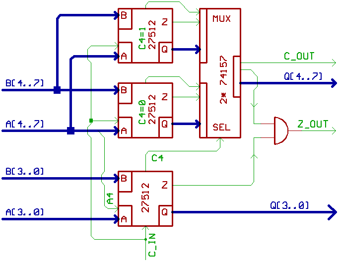
A trick to speed things up is to use three EPROMs.
One for Bit 3..0, two for Bit 7..4.
Two different lookup tables for the two upper EPROMs are needed,
assuming that c_out from Bit 3..0 may be 0, or 1.
The carry output of Bit 3..0 from the lower EPROM
controls 2:1 Multiplexers (74ACT157), for switching
between both of the upper EPROMs.
So we could reach 100 ns with 27512/90ns,
plus the delay of the AND detecting Zero.
Since EPROMs have a three state output, another
(but more expensive) approach is to place some big EPROMs
(like 27040) in parallel, wired as we normally do
with EPROM (program) memory in computers.
Each operating as an 8 Bit wide part of the ALU.
Lookup tables are split up: one chip for logic/shift,
one for add/sub, one for mul/div etc.
But what about the Flag signals ?
All output pins of the EPROMs are used.
Can we get around using two banks of EPROMs,
one for data output, one for generating the Flags ?
One EPROM has 8 output pins,
but there are only a few flag signals.
So we can reserve one output for ZeroFlag_logic/shift,
one output for ZeroFlag_add/sub... and so on, and give them
to a multiplexer (controlled by the chip selects of the other EPROMs)
that gives us finally the ZeroFlag.
Same thing with all the other Flag signals.
A very good implementation of this example
can be found in Dennis Kuschel's "mycpu".
Note, that when mumbling words like "homebrew DSP"
while looking at advertisements for flash memory
sticks/modules, people around you will get confused.
Also keep in mind, that members of the
"puritan TTL Nerd faction" may sneer at you
for juggling with lookup tables beyond 1MB.
[HOME] [UP]/ [BACK] [1] [2] [3] [4] [5] [6] [7] [8] [NEXT]
(c) Dieter Mueller 2004