
Now a few words, how this V_Flag stuff could look like,
when building your own.
First an example, how A+B and A-B are done in hardware:
A+B is easy.
The simplest approach to A-B is to invert B, and to keep the rest like with
A+B.
Inverting B would make B' the one's complement of B.
So for A-B, we have a low_active borrow... but now back on topic.
A close look to the inputs/outputs of the uppermost Bit in our 8 Bit adder:
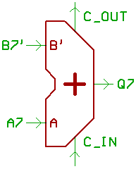
C7 is the carry input for the uppermost Bit, C8 is the carry output.
Now a list, to define what happens on those signals:
| C7= | B7'= | A7 = | C8 = | Q7 = | V = |
| 0 | 0 | 0 | 0 | 0 | 0 |
| 0 | 0 | 1 | 0 | 1 | 0 |
| 0 | 1 | 0 | 0 | 1 | 0 |
| 0 | 1 | 1 | 1 | 0 | 1 |
| 1 | 0 | 0 | 0 | 1 | 1 |
| 1 | 0 | 1 | 1 | 0 | 0 |
| 1 | 1 | 0 | 1 | 0 | 0 |
| 1 | 1 | 1 | 1 | 1 | 0 |
When the V_Flag is active, three conditions are true:
1) A7=B7' and A7<>Q7
2) C7<>C8
3) ( Q7=0 and A7=B7=1 ) or ( Q7=1 and A7=B7=0 )
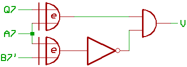
1) XOR/AND:
A fast/good thing when writing emulators.
The VICE for instance uses something like that.
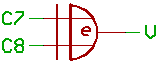
2) XOR
An XOR between Carry input and output from the uppermost Bit in the adder.
The simplest way to go, when you have access to those signals.
Promlem is, when using adder/ALU chips, like 74283 or 74181,
you do not have access to C7.
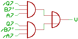
3) AND/OR
When you don't have a carry input/output from the uppermost Bit,
there is a third approach:
[HOME] [UP]/ [BACK] [1] [2] [3] [4] [NEXT]
(c) Dieter Mueller 2005