
The 4017 (also known as CD4017, HEF4017 and MC14017) is a decimal counter
with decoded outputs.
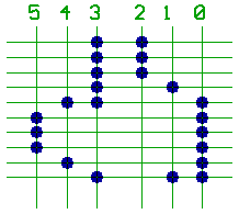
Only one output (Q0..Q9) can be 1 at a time, while all other outputs are 0.
CO is used to cascade such counters, we won't need it for that example.
RES=1 resets the counter to Q0=1, regardless of the signals on CLK and !ENA
(could come in handy, when counting from 0 to something less than 9).
!ENA=0 enables the clock, the counter advances/increments with the rising
edge (transition from 0 to 1) at the clock signal on CLK.
(What could be used to stop the counter, when connected to one of the outputs.
Remember our washing machine sequencer ?)
To generate such a clock, reading the datasheet of the NE555 timer may help.
The outputs of the 4017 can't be directly connected together, so each one
of them big/strange_looking dots represents a diode (maybe 1N4148).
For this example we only use coloured LEDs, but you sure can imagine
optocouplers or transistors for driving light bulbs instead.
Coming to mind, that the resolution of the counter isn't that good.
There are plenty of ruthless drivers out there, ready to slam the gas pedal
if the traffic light gives the imagination of soon turning into green,
and they also show no fear of breaking through the crossing after one
second of red light.
One of our traffic lights tells "decide to stop, or hurry up", while the
other says "prepare to start racing."
You sure can imagine, what will happen, when two of them racing drivers
enter the crossing at such a moment.
Both of them will climb out of their wrecked vehicles, and instantly send
you their lawyers: because it's all your fault.
Now to build a traffic light sequencer with components, that we may meet
again when building a processor.
The 74163 (74LS/F/HCT/ACT163) is a synchronous counter,
with synchronous control inputs.
Synchronous to a rising edge at the clock input CLK.
ENP=1 and ENT=1 enables the counter to increment.
!CLR=0 resets the counter to zero.
!LD=0 sets the counter to the value present at the inputs A..D.
On the 74163, all those things happen only at the rising edge on CLK.
The 74161 has an identical pinout, but resets to zero whenever !CLR=0,
regardless of the signals on all the other control pins.
What means, that if we tie A,B,C,D to 0, !CLR to 1, and use !LD to reset
the counter, we could plug the 74161 or the 74163 into the same socket.
When the counter reached the value 15, and ENT=1, the RCO output is set to 1.
What allows us to connect such counters together to reach multible lengths
of 4 Bit, for a more detailed description read the 74163 datasheet.
The trick would be to allow Bit 4..7 to increment, when Bit 0..3 flips
over to zero.
27C512 (or 27512) is a 64 kB EPROM: 16 address lines, a 0_active chip select
!CS, a 0_active output_enable,
and 8 data outputs that switch to high
impedance if !CS and/or !OE are not 0.
Both components are a little bit overdosed, since we don't need all the
counter functions and all the EPROM memory, but it's just an examle.

The counter runs from 0..15, but note the line from the EPROM output O7
that passes through the inverter, to reset the counter to zero if we have
to.
Now we take the diode matrix from the 4017 example, and turn it into a
list of binary values: replace all the dots with 1 (and all the crosspoints
without a dot with 0).
The LEDs are connected to O0..O5, and O6 is unused (so we set it to 0).
To maintain compatibility with the 4017 example, we can use O7 to mark
an entry as the end of our list, to reset the counter at the start of the
next clock cycle.
(we don't have to count up to 15 as supported by the 74163).
00001100 // 0x0c
00001100 // 0x0c
00001100 // 0x0c
00001010 // 0x0a
00011001 // 0x19
00100001 // 0x21
00100001 // 0x21
00100001 // 0x21
00010001 // 0x11
10001011 // 0x8b
After converting the binary values into hexadecimal, we can burn them
into the EPROM.
And if we did everything right, it should work as with the 4017.
You sure can imagine, how to enlarge/work_over this list for a better
red phase, to keep the lawyers away from you.
Problem is, that, when building a processor, the microcode may become
a lot bigger.
Can you imagine the horrors of manually typing 256 kB of hexadecimal numbers ?
Or the effort for correcting all the typing errors ?
And what, if we unintentionally skipped one single Byte somewhere ?
How to modify such a monstrousity after discovering a design error ?
To prevent enervated programmers from mutating into creatures known
from "Mars Attacks", people built/invented software tools...
Assemblers, for instance.
[HOME] [UP]/ [BACK] [1] [2] [3] [4] [5] [6] [7] [8] [NEXT]
(c) Dieter Mueller 2005