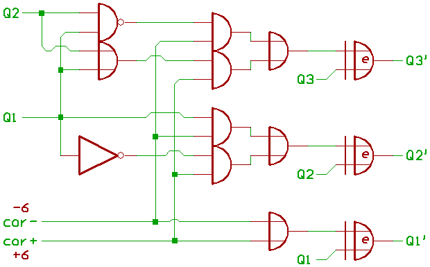
When using 74xx TTL, decimal correction could be done with a 74283 binary adder.
Adding 6 (binary 0110) is easy.
For 4 Bit, subtracting 6 would be the same as adding its two's
complement
decimal 10 (binary 1010).

The OR gate could be removed/eliminated by using the carry input:
we're simply adding 5+1 instead of 6.

When using transistors or logic gates, it isn't necessary to
rebuild a complete 74283.
We could build some half adders instead, and invert the Bits that
have to be corrected:

Now to describe, how it works.
For A+B, the positive maximum is 9+9+1 (when C_IN = 1), or decimal 19.
Q0..3 is the ALU result before, Q0..3' after decimal
correction.
X is Q0..3 XOR Q0..3'.
Now a list for what hapens, if Q is (decimal) 10..19:
   binary binary binary
   Q3..0  Q3..0' X3..0
10  1010   0000   1010
11  1011   0001   1010
12  1100   0010   1110
13  1101   0011   1110
14  1110   0100   1010
15  1111   0101   1010
16  0000   0110   0110
17  0001   0111   0110
18  0010   1000   1010
19  0011   1001   1010
Well.
X0 is always 0,
X1 is always 1,
X2 is equal to !Q1,
X3 is zero, when Q1=0 and Q2=0.
For A-B, the negative maximum is 0-9-1 (when C_IN = 0, active borrow), or decimal -10.
As above, Q0..3 is the ALU result before, Q0..3' after
decimal correction.
X is Q0..3 XOR Q0..3'.
   binary binary binary
   Q3..0  Q3..0' X3..0
-1  1111   1001   0110
-2  1110   1000   0110
-3  1101   0111   1010
-4  1100   0110   1010
-5  1011   0101   1110
-6  1010   0100   1110
-7  1001   0011   1010
-8  1000   0010   1010
-9  0111   0001   0110
-10 0110   0000   0110
X0 is always 0,
X1 is always 1.
X2 is equal to Q1,
X3 is zero, when Q1=1 and Q2=1.
So Q0..3 XOR X0..3 gives us Q0..3', and that's all.
The NMOS 6502 seems to use the same approach.
[2016: edit: this article was written before there was Visual6502.]
[HOME] [UP]/ [BACK] [1] [2] [3] [4] [5] [6] [7] [NEXT]
(c) Dieter Mueller 2006