Once upon a time,
when engineers enjoyed fair working contracts that lasted longer than
twelve weeks,
microprocessors featured three supply voltages at a 4 Bit word length,
and were mostly used in calculators or cash registers.
With only a few thousand transistors a chip, program memory for applications was limited.
Problem is, that microprocessors and end users seem to run on different
numeric formats.
Some simple applications only required to add/subtract fixed point decimal
numbers.
So converting large numbers from decimal to binary (hexadecimal)
and back had a tendency to create an overhead in software.
But there is a trick to make the microprocessor calculate in decimal.
decimal binary hexadecimal
    0    0000   0
    1    0001   1
    2    0010   2
    3    0011   3
    4    0100   4
    5    0101   5
    6    0110   6
    7    0111   7
    8    1000   8
    9    1001   9
   10    1010   A
   11    1011   B
   12    1100   C
   13    1101   D
   14    1110   E
   15    1111   F
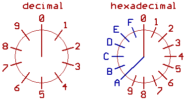
Left: decimal. 0..9, Base 10.
Right: 4 Bit hexadecimal. 0..F (decimal 0..15), Base 16.
When calculating decimal numbers in binary/hexadecimal,
the trick is to skip/avoid numbers between 10..15 (A..F),
and it is called decimal correction.
From the decimal point of view, we may call such numbers
illegal values, or invalid 4 Bit codes...
or, to make it sound more complicated: pseudo_tetrades.
When incrementing 9, the result would be 10 (hexadecimal A).
Adding 6 gives us 0, and a carry that increments the next higher
digit.
So the result would be 10.
When decrementing 0, we would have 15 (hexadecimal F).
Subtracting 6 gives us 9 as a result.
Now to describe, how to build our own decimal correction circuitry in hardware.
[HOME] [UP]/ [BACK] [1] [2] [3] [4] [5] [6] [7] [NEXT]
(c) Dieter Mueller 2006