

|
|
Vacuum Fluorescent Display PSU. By Lee Davison. |
|
 Introduction.
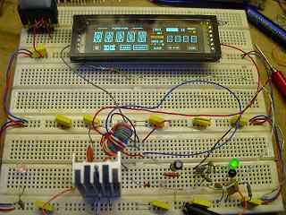
Components.I have quite a few vacuum fluorescent displays that have been rescued from old video recorders, radios, clocks and the like. They aren't difficult to use but do need an AC filament supply and an anode supply of anything from 16 to about 30 volts.
This circuit is a development of the mini switcher and used to provide the AC filament supply and high voltage anode supply for a vacuum fluorescent display from a single 5 volt supply.
All the components are what I had to hand at the time and none of them are particularly critical.
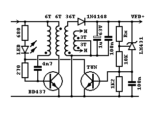
Transistors
The TUN is any high gain small signal NPN transistor such as BC108, BC148, 2N3904 etc and the BD437 can probably be replaced by any near equivalent. In the breadboard prototype the BD437 ran warm so was bolted to a heatsink.
Regulator
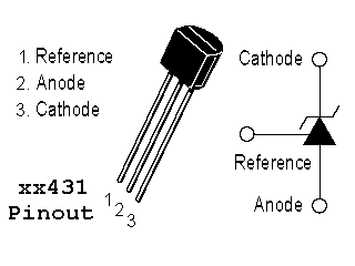
The LM431 is used as a adjustable zener, the voltage being determined by Rx, and is used to set the anode supply voltage up to a maximum of 36V. This device can be replaced by any equivalent such as TL431.
For anode volatges above 36V the LM431 and it's two resistors should be replaced with a zener diode of the required voltage.
Rx
Rx is used to set the output voltage. With the voltage control disconnected the unloaded output is about 40 volts. With the voltage control connected the approximate output voltage is given by ..
Vout = 2.5 * (Rx + 10K) / 10K.. which for Rx = 100K gives about 27 volts out.
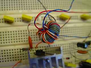
Transformer
This was wound on a small torroidal core using PVC insulated wire and could probably be much smaller and wound on a different shape core such as an EI or even an I core.
The turns count and ratio could be varied if, for example, you need more anode volts without increasing the filament voltage then more turns can be added to the 36 turn anode voltage winding.
The dots on the diagram denote the start of each winding with each winding being wound the same way through the core.
Diodes
A 1N4148 is used to rectify the anode voltage and any diode that can carry a few 10s of mA and withstand a reverse voltage of 100V should work here.
The LED is not at all critical and it and it's associated resistor could be replaced by a single resistor that passes about the same current.
Capacitors
As the anode voltage is generated at quite a quite a high frequency, 750KHz for the prototype, so the rectfier resevoir capacitor is made up of a 1uF 63V electrolytic in parallel with a 100n disc ceramic. A 100n disc ceramic is also used to filter the regulator transistor's base. None of these values are critical.
The 4700pF oscillator feedback capacitor was chosen to give the best running. If this capacitor is made too small the circuit won't oscillate and if it is too large then the transistor has to dissipate a correspondingly large base current. The circuit will work over about a decade of range on this capacitor.
Resistors
The regulator transistor base bias resistor, which is 1K2, must be less than a fifth of the value of the LM431 reference voltage resistor, 10K in this case.
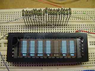 VFD pin identification.
If you have a VFD and not it's pinout this PSU can be used to easily identify each electrode pin. The display is connected to the filament supply, usually the two end pins, and all of the other pins are connected, each via a 100K resistor, to the anode supply.
Connected like this all the segments in all the digits ahould light and as each pin is grounded in turn the corresponding segment in each digit, for a segment pin, or the corresponding digit, for a digit grid pin, should extinguish. On some displays some digit grids may connect to more than one pin and the digit will extinguish when either of these pins is grounded.
| Last page update: 15th July, 2006. | e-mail me
 |