

|
|
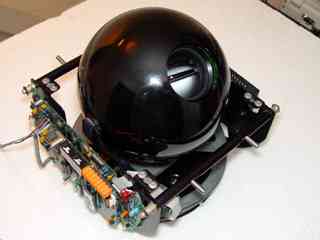
SpeedDome PTZ camera. By Lee Davison. |
|
 Introduction.
I picked up this camera for not very much money last November at the North Wales Radio Rally. I had been eyeing up an identical model on another stall but that was fifty five quid and one of the PCBs had very obviously been smashed. This one was forty quid less and on the 'Bring & Buy' stall. When I got there one of the traders seemed interested and was trying to haggle them down to a tenner. Fortunately for me they said they'd have to ask the seller and to come back later, so as soon as the trader left I offered the asking price so now it's mine. . . . . MINE!
Sooooo .... Now what? Take it apart of course! While doing this two problems were noticed, first the tilt motor had some play in it's gearbox output shaft, and second the pan mechanism was seized almost solid, bugger! An hour and a half, two cups of tea, many misused tools, mostly hammers and drills, and much swearing later the whole mechanism was apart and the problem could clearly be seen. The ball bearing which supported the pan mechanism had been lubricated with what looked like a mix of salt water, grit and plaster. Now I knew why it had only been fifteen quid.
At this point there were two plans. Plan A was to replace the ball bearing with a new one saving much time and effort and assuring faultless operation, at least for a while, and plan B was to spend two hours in a freezing garage using any solvents I could find and an old toothbrush to clean as much crap out as I could, stuff the bearing with grease, and put it back in. A little work with the yellow pages and I found out a new one would cost 28 notes plus VAT, and that was only because they had one sitting on the shelf and offered it to me at only 33% of the list price just to get rid of it. Plan B it was then.
Plan B actually worked very well using a series of succedingly volatile solvents in an enclosed space, well it was damn cold, sod opening the windows, and an inspection of the tilt motor gearbox revealed that while there was some play it was the shaft that had worn, not the easily replaced plain bearing, and it didn't really matter as it was less than the backlash in the gears. So the whole thing was re-assembled.
 It's alive!.
What's next.So now I have a fifteen quid eyeball that I can pan and tilt freely, I need to wire this puppy up to something. First problem was the power requirements, 24VAC. I was sure I had a 25V transformer somewhere and eventually found the unlabeled thing. Just to be sure I wired up the mains to it and put the meter on the output .... 41VAC, nuts! Much searching later and a 25V torroid is borrowed from elsewhere and a mains lead connected. Call me paranoid but the meter was pressed into service again, just to be sure, and again read 41VAC. Double nuts! Much more searching and my old Fluke DVM was dragged out of the cupboard and, with a new battery installed, pressed into service. It read 25VAC from both the torroid and from the transformer I first tried.
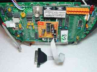
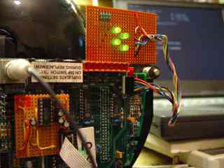
On the logic board the power connector had been damaged and I didn't have a matching plug so it was removed and the three wires for the power soldered directly to the PCB as you can see in the top left of the picture. No real loss, I can always change that to screw terminals or similar if needs be. Power was applied and, after a few heart stopping seconds while it sorted out all it's processors, five in all I think, the dome tilted and panned to it's 'home' position and then back to the position it had last been in when powered. It works!
P4 - AC PWR IN / DATA I/O Pin Colour Function P4 is the remote connection to the SpeedDome and carries the power and data signals. In this case only the power connections have been connected and only the two AC lines are used but here is a table of the pin assignments and wire colours for all the pins on that connector.
1 Brown Data out - 2 Yellow Data out + 3 Black AC 4 White Gnd 5 Red AC 6 Green Data in - 7 Orange Data in +
Connecting.Now to get it to talk to the rest of the world. A search of the net revealed that the SpeedDome, along with many other PTZ cameras, talks serial but RS422 serial and not the more PC friendly RS232 variety. I was going to make an RS422 to RS232 convertor that would need to be RS422 to TTL then TTL to RS232 when I realised that one of only two socketed chips on the top board was the RS422 buffer, a-ha! Just make an RS232 daughter board to fit in it's place.
RS232 Interface board
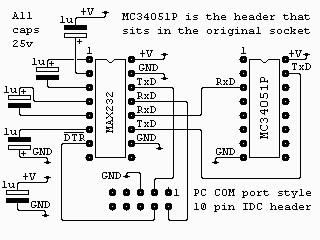
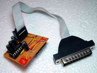
The circuit itself is verty simple, just a MAX232 and five capacitors. The board has a dual in line header, mounted under the board, that plugs into the now vacant MC34051P socket on the SpeedDome and it connects, via a ten way IDC header, to a PC COM port plug. The MAX232, 16 pin DIL header and the ten way IDC header are all shown, as mounted, looking down onto the board from above.
LED indicator board
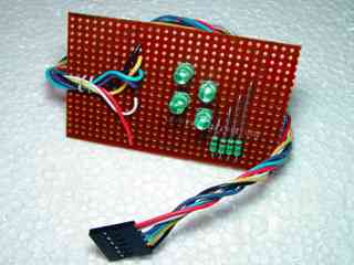
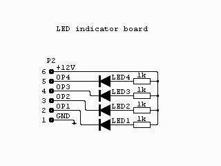
There are four open collector outputs available on P2, the aux connector, so an indicator board was made up with four LEDs and four resistors. Note that being open collector outputs the LED cathodes go to the output and the anodes go, via current limiting resistors, to the +12v supply.
RS232 board fitting
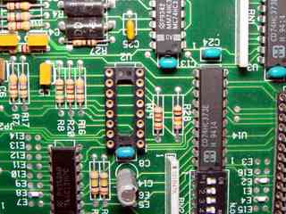
If U2, the RS422 buffer, is socketed as mine was it's a simple job to remove it and fit the RS232 board in it's place. Take care to note the orientation of the devices, in all the pictures her the SpeedDome is shown upside down as it is actuall a ceiling mounted device resting on a desk.
The 25VAC power, at .78 Amps according to the label on the mechanism, was connected to the AC connections on P4. The Ground connection was not connected in this case but could be connected to earth or to the DC ground of any other equipment you are using with it.
The BNC connector is video out, 1V pk-pk into 75ohms and, for this camera, is CCIR PAL 625 line 50 field
The SpeedDome is connected to the COM port on a PC via a null modem lead. The settings should be 4800 baud, 8 bits, no parity and one stop bit. The LED indicator board is connected to P2, the AUX connector. This would usually be used to control ancilliary equipment such as lighting or the latches on doors monitored by the camera.
All that's required now is some software to drive the camera and that can be found here.
| Last page update: 28th January, 2005. | e-mail me
 |