
 |
Sampled sound card. By Lee Davison. |
 |
 Introduction
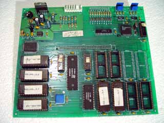
Finding soundsAnother found at a radio rally for not very much money thing. The legend on the card says BWB NEWARK LTD. VSS3 SAMPLED SOUND PROGRAM CARD MK3 but apart from that I have no real info. I grabbed this because I thought the 27C4000 EPROMs would come in handy and there were some other interesting chips on the board. One of the first things I did with the card was to read out the programmable logic devices and the EPROMs.
Four of the EPROMS, labeled MGD_SND_.2_A, B, C and D, are connected to an OKI MSM6376 speech chip and I wanted to know what sounds there were in these EPROMs. While I could find datasheets for similar chips, including chips from the MSM6375 family, they all lacked any information of the format of the stored data, apart from that it is ADPCM encoded.
AddressesLooking at the contents of the sound ROMs in turn, the A ROM seemed to start with some sort of table then just random data, sound ROMs B and C seemed to be just random data and ROM D differed from B and C only in that most of the last half of it is unprogrammed.
It seemed to make some sense to combine the ROMs to make one big data image and this was done with the ROMs in the order A, B, C and D.
ADPCM SamplesWith the ROMS combined to form one data image it quickly became evident that the table at the start is a table of addresses as all the values fall within the range of the data. Starting at the fourth byte in they were taken as a series of longword addresses in big-endian format, high bytes first. The address of the first sample is shown in bold.

These continue until a longword zero is encountered, this marks the end of the sample addresses. This again is shown in bold.

Each address points to the start of a sample, this is the start of the sample pointed to by the first address ...

Before I discovered that the data was ADPCM encoded I did try to play the samples as just binary data. For the first sample that produced this awfull noise.
000220.wavraw data as a .wav file.
SamplesOnce I found some data on the voice chip I realised that the samples would need further work before they sounded correctly. Using ADPCM decode algorithms made the sounds more coherent but something wasn't right. The sample DC levels would drift leading to positive or negative clipping and there were discontinuities in the output waveform. Looking closer at the data I realised that not all of it was sample sound data.
Samples are made up of blocks, a block consists of a length byte with bit 7 set followed by a number of sample bytes ...

The end of a sample is signified by a null block length byte with bit 7 clear. In the case of the first sample the last block, from address $004020, has a length of $16 bytes and is followed by the zero end marker. The next byte is the start of the second sample's first block.

Without the block length bytes in the data stream the samples began to sound much better but there was still drift in the DC levels and the samples would either clip badly when decoded as eight bit, or would be very quiet when decoded as 16 bit. No ammount of adjusting the decoder gain and offset would cure everything, I even managed to get some samples mostly too quiet with clipping in the loud sections.
It had to be easier than this, so back to the web and further trawling found this bit of information ..
"Dialogic ADPCM is a variation of the standard IMA ADPCM algorithm that is optimized for monaural voice data. The encoder operates on 12-bit input samples and outputs 4-bit encoding for each sample."
.. it also gave the modified IMA decode tables. These were plugged in to the decode program and the limits set to clip on 12 bit data, this worked with no appreciable DC drift and almost zero clipping. The data thus generated was then scalled up to 16 bit, and down to eight bit, to give .WAV format data.
Decode softwareHere is the first sample as an 8 bit, and 16 bit, .WAV file.
000220.wav8 bit .WAV sample. 000220.wav
16 bit .WAV sample.
FutureBoth versions of the software are very similar, the main difference is that for the 8 bit .wav data is scaled from unsigned 12 bit uncompressed data whereas the 16 bit .wav data is scaled from signed 12 bit uncompressed data.
The input file name for the program is fixed as snd_2.rom, there was only ever the one input file. The output file names are the start addresses, in hex, of each sample within the input file with .wav appended to them.
View the 8 bit conversion source, view the 16 bit conversion source or download
both sources as a .zip file
I now have the datasheet for the OKI MSM6376 speech chip but it doesn't give any information about the ROM data format. So what still remains to do is to find out what the remaining bytes, between the end of the address table and the start of the first sample, in the sound ROM are. After that it should be fairly easy to generate new data for a new set of sound ROMs.
| Last page update: 29th March, 2007. | e-mail me
 |