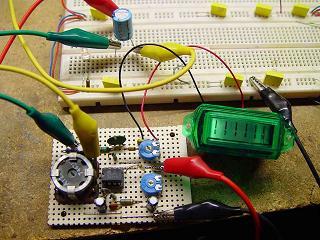
 Introduction.
Electrolytic capacitors go wrong. An engineer I used to work with once said that as long
as there were electrolytic capacitors there would be jobs for engineers. He was right.
An ESR meter is a meter that can be used to test the ESR of electrolytic capacitors,
along with other components and can become an invaluable tool in the engineers toolbox.
What is ESR?
No capacitor is perfect, as well as its capacitance it will also have some inductance and
some resistance and it is equivalent series resistance, which is like having a resistor
in series with an otherwise perfect capacitor, that can come to dominate in a failing
capacitor. As this resistance increases ripple current, which in switch mode power
supplies can be many amps, causes the capacitor to heat up due to resistive loses and
this heating accelerates the demise of the capacitor by drying out the electrolyte at a
faster rate.
A good capacitor of 1uF or more may have an ESR of less than one ohm but as it ages this
value will increase to many ohms and even many tens of ohms. The life for an electrolytic
capacitor depends on the quality of construction, its ripple current and the temperature
that it is operated at and can be as little as a few thousand hours in some cases.
|
 The circuit.
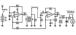
The circuit is really quite simple. One half of the TL072 is configured as a relaxation
oscillator oscillating at about 100KHz. The output from this has its DC component
removed by a 100uF electrolytic capacitor before being fed to the primary of a small
step down transformer. This transformer performs two functions, it reduces the signal
amplitude from over 4V peak to peak to about 200mV peak to peak and reduces the
impedance from around 300 ohms to less than one ohm. The 10 ohm resistor across the
output of this transformer acts as a minimum load to reduce output level variations.
One consequence of having such a low voltage low impedance signal source is that the
capacitors can usually be tested without removing them from circuit.
This test signal is applied to the capacitor under test and returns via a 2.2 ohm
resistor with which it forms a voltage divider. The voltage across this resistor is
amplified by the other half of the TL072 before being rectified and smothed and then
applied, via an adjustable resistor, to the 50uA meter. As this voltage is inversely
proportional to the series resistance of the capacitor the lower this resistance the
greater the defelection of the meter.
|
 Construction.
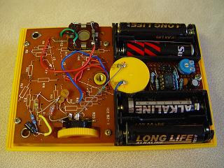
Construction is not critical and, as some components like the transformer core were
selected from what was available at the time, a printed circuit board is not really
practical. The first two prototypes were built entirely on stripboard, the last one
partly on stripboard and partly on the remains of the donor multimeter circuit board.
The 100K pot in the circuit is any subminature type but the adjustable meter series
resistor should be easy to adjust by hand as its setting will need to be varied to set
the meter zero which will depend on the leads used with the meter and the age of the
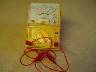
batteries. In the old multimeter used for the last version there was such a pot already
present and this, along with a fixed resistor, was used as the meter series resistor.
|
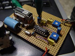
The transformer can be wound on any small ferrite core that has room for all the 400
primary turns and the 20 secondary turns. The actual core used is not critical, almost
any ferrite core will do, and the small feedback tranformers in computer power supplies
or the output transformer from a cold cathode fluorescent lamp inverter would be ideal.
The first prototype and this version used the core from an audio filter inductor while
the second prototype, seen here, used a transformer that already had two ten turn
windings that were used in series and a winding with many hundreds of turns that was
unwound until only about four hundred turns remained.
No special care needs to be taken winding the transformer, I wound the secodary first
and then wound the primary directly over it using 30 SWG, 28 AWG, coated copper wire
for both the primary and secondary.
How yet another transformer was made is detailed on its
own page.
|
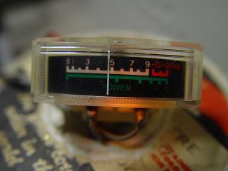
The meter is also not critical, Any meter that is sensetive enough, i.e. 150uA or better,
can be used. The first prototype used a tuning meter from an old FM receiver, the second,
shown here, used the signal strength meter from a CB radio.
The series resistor to the meter should be chosen to suit the meter, the better the
sensetivity the higher value it should be. In the first prototype this resistor was only
10K ohms but for the 50uA multimeter meter the original 39K ohms adjustable resistor was
reused along with a 27K fixed resistor to give a usable range.
If a resistor of much more than 47K or so is needed for the meter the gain of the
detector stage can be reduced instead by reducing the value of the 47K feedback
resistor between pins 6 and 7 of the TL072.
|
 Setting up
Before powering the first time the 100K preset pot should be set to about midway, the
meter series resistor should be set to maximum and the test leads should be connected
together. If all is well when the circuit is powered the meter should show some
deflection and this should be adjusted with the meter series resistor to give a reading
near full scale. Now the 100K preset pot should be adjusted to give the maximum reading,
this should not be far from the position it is already set at.
Now the meter should be closed up and, with the leads still connected together the meter
series resistor adjusted to full scale. That's it, the meter is now ready to use.
Calibration
Once the meter is set up and working you may wish to make a calibrated scale for it. The
easy way to do this is to use a series of good accuracy, say 1%, low ohm resistors and
testing each in turn mark its value on the meter scale. You can then photograph or scan
this scale and use it as a template to print out a new scale for your meter. In the case
of this meter the original ohms scale, although reading ten times the actual value, is
close enough to be used at is.
|
 In use
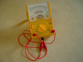
One feature of an ESR meter such as this is that in almost all cases it can be used to
check capacitors without removing them from circuit but not while the circuit is still
powered, especially mains filter capacitors. This is because of the low voltage
test signal and because a good capacitor will be almost a short circuit, so any other
components connected connected to the capacitor will have a minimal effect on the
measurement. The one case where this is certainly not true is when trying to measure
one of the many parallel capacitors such as supply decoupling capacitors on a logic
board.
|
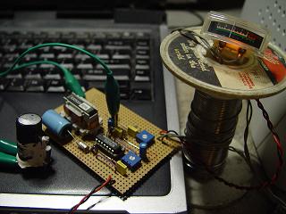
The use of the ESR meter does not stop at testing capacitors though. It can also be used
to test for shorted junctions in semiconductors such as switching transistors in switch
mode power supplies and cold cathode fluorescent inverters or failed diodes in a bridge
rectifier or diode stack. Instances where a standard ohms meter and even a diode tester
can give uncertain results. It can also be used to some extent to test ferrite cored
inductors and transformers for shorted turns. In this case an open circuit is a good
thing as it shows that the inductance of the test subject is large enough to be a
significant impedance at the test frequency.
These features can make an ESR meter an essential tool for troubleshooting electronic
equipment.
|
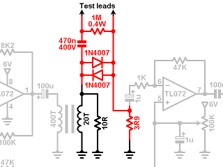 400V input protection
Sooner or later I'm sure I'll try to measure the ESR of a capacitor that is charged or
even still powered. This modification should go some way to protecting the meter from
being damaged by this kind of mistake.
The added components, shown in red, are a 400V 470nF unpolarised capacitor to block any
DC voltage and two back to back 1N4007 diodes to divert any charging current for this
capacitor away from the transformer and associated components. Finally a 1M ohm 0.4W
resistor is added across the test leads to dissipate any charge on the 400V 470nF
capacitor.
In normal use the two back to back 1N4007 diodes never conduct so have no effect on any
measurements made and the 1M ohm resistor likewise is far too large to matter. The 400V
470nF capacitor does change the signal source impedance a little and to compensate for
this a 3.9 ohm input resistor, also shown in red, replaces the original 2.2 ohm resistor
to keep the scale calibrated.
|
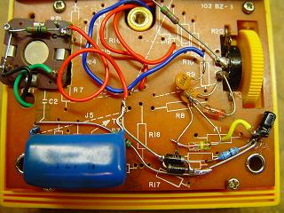
Any of the 1N400x range of diodes could be used, I used 1N4007s because that's what was
to hand at the time. The maximum reverse voltage they ever see will only be the forward
voltage of the other diode, so there is no need for high reverse voltage parts.
The added components were fitted onto the remains of the original multimeter circuit
board. The 1M ohm discharge resistor can just be seen underneath the 400V 470nF capacitor
and alongside those are the two back to back 1N4007 diodes. All the added components fit
easily within the donor multimeter case.
|


 Introduction.
 The circuit.
 Construction.


 Setting up
 In use

 400V input protection

