
 |
LED flash. By Lee Davison. |
 |
 Introduction.
I like free things, or at least no money things and, in a deal with my ex-employer that saw the exchange of some
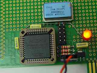
old shiquality NOS microprocessors for some programmable logic, I finally got all the bits together to try CPLD programming with the 8 Bit Baby.This circuit, being the first 8 Bit Baby project, is made deliberately simple, mostly so that there is less to go wrong but also because I'm lazy and I wanted something to show for just a little work. Apart from the 8 Bit Baby, the programming lead and software all that's needed is an LED, a resistor and an 8 bit computer to plug it into or, lacking that, an XTAL oscillator and a socket.
 The circuit.
The design.Yes that's it. Even I can't mess that up1. The circuit works by taking the clock input, which is either Ø2 from the host CPU or one to two MHz from an XTAL oscillator, and divides it by 1048576 to give a roughly one Hz flash rate.
As I didn't want to make room on the bench for a Vic 20 or C64 I decided to go with the XTAL oscillator. For this a socket was mounted on the 8 Bit Baby and wired to the +5v, ground and the EPM3064. The LED was fitted and a short bridge soldered between the anode and the +5v and finally the 270 ohm resistor was fitted with one end soldered to the LED cathode and the other to pin 6 on the EPM3064.
Making it work.The design uses three cascaded 8 bit synchronous counters to make a 20 bit divider. The first counter is enabled continuously and the carry out from that counter is high for one count in every 256 counts. This carry signal is inverted and used to enable the second counter so that it only counts once in every 256 cycles. The carry out from this counter is again inverted and used to enable the third counter, this counter only counts once in every 65536 cycles and the fourth output bit from this counter, that changes state every 524288 cycles, is used to drive the LED output pin giving an overall ratio of 1:1048576
Creating a design.To make the EPM3064 do anything first you have to program it. To do that I use Altera's Max+Plus II software that is available 'free' rrom the Altera website. 'Free' in this case means no money, but you do have to fill in Altera's online registration. Eventually these companies will learn that if you want to have the best selling product then you don't just make the software for that product free, you actively give it away to anyone - even if they may not be interested. Well it worked for [REMOVED].
Assuming you managed to download Max+Plus II and get it installed what follows is a fairly quick how to guide. Images with borders can be clicked to open the image, full size, in a new window.
That's it. If everything went to plan, the LED was already connected and it was in the target system or an XTAL oscillator was connected, then the LED should start flashing as soon as the programming is complete. It's Alive!
If you can't be bothered to enter the design, or it didn't work for some reason, here's
one I made earlier.
[1] Yes I can.
| Last page update: 4th March, 2006. | e-mail me
 |