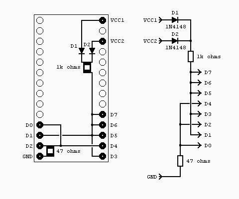
Here's a simple circuit, built from bits in the junk box, that has saved many hours of
head scratching when that just finished new 6502 circuit failed to work first time.
What does it do? Well nothing much, in fact a lot of nothing much's as it pulls the data
lines on a 6502 to the NOP ($EA) opcode.
The circuit is built on a small piece of stripboard that has been soldered onto a 28 pin
turned pin I.C. socket. This is the only important part of the project, use decent (i.e.
stiff and thin) pins. Don't be tempted to use IDC header type pins, as they are too thick
and will ruin the socket you push them into. If you have them use I.C. header pins, I
didn't but a turned pin socket, used as a header, is just as good.
The two diodes, I used 1N4148s but any small signal or shottky diode will do, are to
allow the use of this generator in either 24 or 28 pin sockets. If you are only ever
going to use one type then the diodes can be omitted and the 1k resistor tied directly
to the +5v pin.
6502 NOP generator circuit.

The 1k resistor is used to pull up the five data lines that need to be at logic 1, I
could have used five 4k7 resistors but I'm lazy. This works just as well.
The 47R resistor in the pull down path is just there to limit any possible ground path
fault current to around 100mA, while still providing a firm logic 0 to the data bus.
Any value from 33 to 100 ohms should do just as well.


