Address Decoding
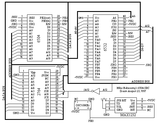
The 6504 has an 8K address space using address lines A0-A12. A12 is connected to the inverter and when high is inverted to select the EPROM as the upper 4K bank. A12 is also connected directly to the chip select (/CS) of the 6532 RIOT. A7 is connected to the RAM select (/RS) of the RIOT. The RIOT's I/O section is activated when /CS is low and /RS is high, and the RAM is turned on by /CS low and /RS low. Here is a truth table of the computer's address decoding:
A12 A11 A10  A9  A8  A7  A6  A5  A4  A3  A2  A1  A0
--- --- ---  --  --  --  --  --  --  --  --  --  --
 1   X   X   X   X   X   X   X   X   X   X   X   X  = EPROM
 0   X   X   X   X   0   X   X   X   X   X   X   X  = RAM
 0   X   X   X   X   1   X   X   X   X   X   X   X  = I/O
In the table, X = "don't care". This logic puts the EPROM at $1000-$1FFF. Since this is the top of memory, the reset and interrupt vectors are located here, in the same order as on a standard 6502. The 6532 RIOT I/O is addressed at $0080 and has many mirrors. This permits zero-page addressing of the system I/O ports. The only RAM for this simple computer is contained in the RIOT chip and is 128-bytes in size. Like the I/O, the table shows that the RAM has many mirrors in memory. The RAM can be addressed starting at $0000. Note, however, that the stack also shares this 128-byte space. Normally, the microprocessor expects the stack to be a full 256-bytes of RAM in page 1 ($0100-$01FF). However, in this design our RAM is only mirrored at $0100-$017F. The stack pointer must be initialized to $017F by the system software for the stack to function and commands like JSR/RTS to work correctly. Keep in mind that the stack and user RAM are 128-bytes of shared memory. User memory should should be accessed starting at $0000 for faster zero-page addressing, although using the mirrors such as at $0100 is perfectly fine. The stack starts at $017F and builds downward in the 128-byte space, so keep variables low and be careful not to collide with the stack.
Building the Computer
Making the 6504 board requires the parts listed in the Components summary. Many of the parts are common and can be found in most electronics stores and mailorder outfits. These include the 7404 inverter, 1.000 MHz crystal oscillator, and 2764A EPROM. The MAX1232 reset circuit is also available from Dallas Semiconductor as the DS1232, although the Maxim datasheet says their product consumes 1/10th the power of the Dallas part. The 6504 and 6532 will be harder to find, you'll have to check your catalogs. I have seen them in the Jameco Electronics catalog in the past. If you can't locate them, I have pulled them from old equipment such as the Commodore 4022 printer which has a 6504 and two 6532s. If all else fails, go to garage sales and find yourself an Atari 2600 and desolder the 6507 and 6532. Note that the numbers on the chips may be different. The 6507 will be the only 28-pin chip on the board and the 6532 may be labelled with "CO10750". Be careful not to grab the other 40-pin chip instead, this is the TIA (Television Interface Adapter) for video output. The 6507 will plug right into the socket for the 6504, however it does not have IRQ, instead the pin is RDY. Just pull it high and if you do get a 6504 to replace it connect the IRQ pin to the 6532 IRQ output. The 6507 can actually be directly subsituted for a 6504 in this circuit, but software absolutely cannot toggle the IRQ interrupt because it will trigger the RDY line on the 6507. If you manage to locate a 6532 RIOT but not the 6504 or 6507, a regular 6502 (very common) may be used. The pins assignments will be different because the 6502 is a 40-pin package, so you'll have to make adjustments accordingly. The higher address lines (A13-A15) should be left disconnected. Like on the 6507, the RDY line should be pulled high. Also, a 6502 will give the added bonus of NMI-type interrupts if you find a use for them. Hopefully with any luck you will be able to find the 6504 and 6532 and build the project as described. The Test Program is designed to work with any of these setups. If you don't already have them, here are pinouts of the main chips:
     +---+  +---+                +---+  +---+             +---+  +---+
/RES |1  +--+ 28| PH2 out    Vpp |1  +--+ 28| Vcc     Vss |1  +--+ 40| A6
 Vss |2       27| PH0 in     A12 |2       27| /PGM     A5 |2       39| PH2 in
/IRQ |3       26| R/W         A7 |3       26| NC       A4 |3       38| CS1
 Vcc |4       25| D0          A6 |4       25| A8       A3 |4       37| /CS2
  A0 |5       24| D1          A5 |5       24| A9       A2 |5       36| /RS
  A1 |6   6   23| D2          A4 |6   2   23| A11      A1 |6       35| R/W
  A2 |7   5   22| D3          A3 |7   7   22| /OE      A0 |7       34| /RES
  A3 |8   0   21| D4          A2 |8   6   21| A10     PA0 |8   6   33| D0
  A4 |9   4   20| D5          A1 |9   4   20| /CE     PA1 |9   5   32| D1
  A5 |10      19| D6          A0 |10      19| D7      PA2 |10  3   31| D2
  A6 |11      18| D7          D0 |11      18| D6      PA3 |11  2   30| D3
  A7 |12      17| A12         D1 |12      17| D5      PA4 |12      29| D4
  A8 |13      16| A11         D2 |13      16| D4      PA5 |13      28| D5
  A9 |14      15| A10        Vss |14      15| D3      PA6 |14      27| D6
     +----------+                +----------+         PA7 |15      26| D7
                                                      PB7 |16      25| /IRQ
                                                      PB6 |17      24| PB0
                                                      PB5 |18      23| PB1
                                                      PB4 |19      22| PB2
                                                      Vcc |20      21| PB3
                                                          +----------+
Start by placing sockets for all of the chips on the board. There are
two 28-pin sockets for the 6504 and 2764A, one 40-pin socket for the 6532, a 14-pin
for the 7404, and an 8-pin for the MAX1232. You may elect to put the crystal
oscillator in a 14-pin socket or just solder it to the board. Connect
all of the Vcc (+5V) pins and Vss (GND) pins. On the oscillator (full can version),
Pin 7 = GND, and Pin 14 = +5V. An connect to your power supply. You may or may
not choose to put a voltage regulator onboard, either way put a 10uF capacitor
between +5 and GND on the board where the power comes in. After connecting all of
the power and ground connections, install a decoupling
capacitor of .1uF close to each IC connected between Vcc and Vss.
Next, connect the output of the oscillator (pin 8) to the 6504 PH0 in (pin 27). Build the reset circuit as shown in the MAX1232 datasheet and connect the output to the /RES input on the 6504 (pin 1). Connect A12 from the 6504 to the input of an inverter, and the connect the inverted output to /OE and /CE of the EPROM. Tie /PGM and Vpp on the 2764 EPROM to Vcc (+5V). Connect A12 of the EPROM to GND, or install a switch to toggle it between +5V and GND to select between two 4K halves. Grounding A12 enables only the lower 4K half of the EPROM. On the 6532 RIOT, tie CS high and connect A12 of the 6504 to /CS of the RIOT. Also connect A7 from the 6504 to /RS to the 6532 RIOT chip. Connect /RES on the 6504 to /RES on the 6532, and also connect /IRQ from the 6532 to /IRQ on the 6504 with a pull-up resistor of 5-10K to Vcc. Connect PH2 out from the 6504 to PH2 in on the 6532, and then connect R/W from the 6504 to R/W of the 6532. The only connections left are the address and data lines. A0-A11 of the 6504 go to A0-A11 on the EPROM. A0-A6 on the 6504 connect to A0-A6 on the RIOT. D0-D7 are connected on all three chips.
That's it! If all of the connections are made correctly and no shorts or other mistakes have been made, you're ready to assemble the Test Program and check out your new toy. Good luck!
Schematic Drawing

The schematic may be download as 6504SCHM.GIF.
Missing from this drawing are the .1uF decoupling capacitors, one located close by each IC. There should also be pull-up resistors of about 5-10K on the /RES and /IRQ lines to Vcc. The ports of the 6532 RIOT have been left open; add whatever hardware you wish.
I drew this schematic using the demonstration version of Protel's Advanced Schematic software. I have found this to be an excellent package and it took me only a few hours of tinkering to learn how to use it. Visit Protel's website at www.protel.com for more information.
A Simple Test Program
Programs are written in standard 6502 assembly language and are usually written with a cross-assembler like TASM. Sometimes I also write my 6502 programs on my Commodore 128 personal computer, where it is easy to test the code before putting it on an EPROM. For PC users, there is a 6502 simulator which will aid in debugging your programs. After assembling and debugging programs they can be burned onto an EPROM and executed by the 6504 computer board. An EPROM Emulator is a very handy device that can save you plenty of time and frustration if you are lucky enough to own one. Here is a simple test program that runs on the bare board once constructed to verify its operation with a logic probe and/or oscilloscope. It runs an 8-bit counter on both Port A and Port B of the 6532 RIOT. The program resides in the $1000-$1FFF area on the system memory map. After assembling the binary (or downloading it from here), burn it into the lower half ($0000-$0FFF) of a 2764 EPROM. Since A12 of the 2764 is grounded, the region of $0000-$0FFF on the 2764 is equivalent to $1000-$1FFF in the 6504 system addressing scheme.
;6504 Homebuilt Test Program

.ORG $1000

RESET:      sei            ;Disable Interrupts
            cld            ;Binary Arithmetic Mode
            ldx #$7f
            txs            ;Initialize Stack Pointer
            cli            ;Re-enable Interrupts
            lda #$ff
            sta $81
            sta $83        ;Set Ports A & B for All Outputs
            ldx #$00
            stx $00        ;Start Counter at 0
LOOP:       jsr DELAY      ;Call for a Short Pause
            brk            ;Just to Test Interrupts
            .BYTE $00      ;One byte fills hole after BRK
            ldx $00        ;Get the Count
            stx $80
            stx $82        ;Put Count on Ports A & B
            inx            ;Increment the Count
            stx $00        ;Store the Count
            jmp LOOP       ;Do it all again!
DELAY:      ldx #$ff       ;Begin Delay Subroutine
            ldy #$ff
WAIT:       dex
            bne WAIT
            dey
            bne WAIT       ;End Delay Subroutine
            rts

.ORG $1E00
IRQ:        rti

.ORG $1FFC
.BYTE $00, $10 ;Vector to Reset
.BYTE $00, $1E ;Vector to IRQ

.END
This program is available as an assembled binary as 6504ROM.BIN.
You can now use your logic probe to test the I/O ports of the RIOT as the counter program increments the count on the ports. You can also use an oscilloscope and probe to observe the operation of the other signals. Hopefully if everything is constructed correctly it will work as perfectly as mine does.
Once you get it working, many of the mini-projects on 6502.org can be used with it. You might like my interfaces for the X-10 CM-17A Firecracker and Sharp GP2D02.
Pictures of the Hardware


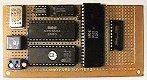
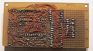
These photographs were taken using a Casio digital camera. At top left you can see the TTL crystal oscillator, just under that is a reset button and power input. If you look carefully you can see the text written on the 6504 CPU, and below it is the EPROM with the system software. Above these two 28-pin chips is the 8-pin MAX1232 and a 14-pin 7404 inverter. The large chip (40-pin) is the 6532 RIOT, and to its right is a 20-pin socket I used to connect the 16 I/O lines to other boards and projects. The rest of the board has been left open for future modifications or expansion. The second picture is the underside of the project, which uses #30 wirewrap wire and point-to-point soldering for all connections.