An experimental attempt of building something like a 6545\6845
with 74XX TTL chips.
The design certainly has some issues,
But it isn't impossible to generate a video signal with it...
Try reading the schematics at your own risk.
ATN:
X45 generates a 16 Bit video address,
and from the timing specifications,
it outputs said address faster than a 6545\6845.
Because of this, the X45 video address is emitted
by 74573 latches, what gives you a chance to tweak
the timing a little bit if necessary.
Needless to say,
that the load signal for those latches should be high,
and that the output enable for those latches should be low
for getting a valid video address...
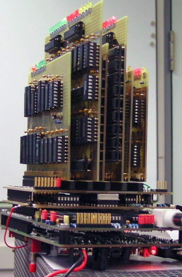
Test setup:
Bottom: my DRC2 SBC, which is supposed to be compatible to the SBC-2.
D45 demonstrator is plugged into DRC2.
X45 backplane is plugged into D45.
Plugged into the X45 backplane, we have:
1* B45, bus interface
1* C45, the control module
1* T45, horizontal\vertical timing module
1* R45, raster timing module
2* G45, two video address generator modules
Note the thin red wire at the left:
it is necessary to run the CPU with a 2 MHz clock,
which is generated from the D45 demonstrator.
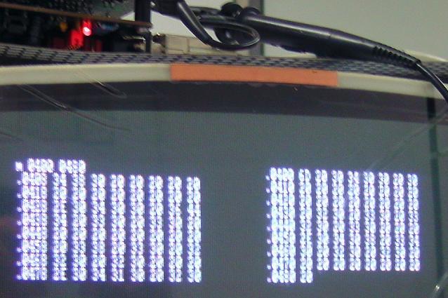
80*25 text,
2 MHz clock,
15.625 kHz horizontal,
50 Hz vertical,
8 raster lines per character,
non_interlaced.
Ignore that odd text format:
Software does 40*25 text, hardware does 80*25 text.
Register settings:
R0 =0x7F
R1 =0x50
R2 =0x5E
R3 =0xAA // it's just a guess...
R4 =0x26
R5 =0x00
R6 =0x19
R7 =0x1F
R8 =0x00
R9 =0x07
R12=0x04
R13=0x00
Todo: check, if this is compatible to a real 6545\6845...
The register settings are just a guess, of course,
because I was happy to eventually get a video signal at all...
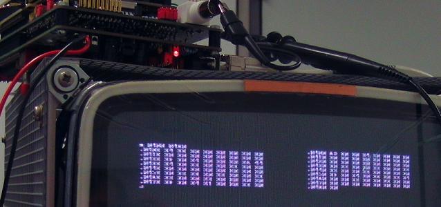
80*50 text,
2 MHz clock,
15.625 kHz horizontal,
50 Hz vertical,
8 raster lines per character,
interlaced.
Register settings:
R0 =0x7F
R1 =0x50
R2 =0x5E
R3 =0xAA // it's just a guess...
R4 =0x4D
R5 =0x00
R6 =0x32
R7 =0x3E
R8 =0x03
R9 =0x03
R12=0x04
R13=0x00
Issues:
Looks like there is a conceptual mistake in the circuitry
of the raster address counter\comparator...
but fixing this most certainly will cause _other_ issues...
Also, there is a problem with R5, vertical total adjust.
0x00 will work correctly: no additional raster lines inserted.
For all other values, one raster line is inserted too many...
BTW: Light pen interface isn't fully tested.
X45 supports straight binary addressing mode (normal 16 Bit counter)
and row\column addressing mode (8 Bit counter row, 8 Bit counter column),
depending on register 8 Bit 2.
D45 demonstrator
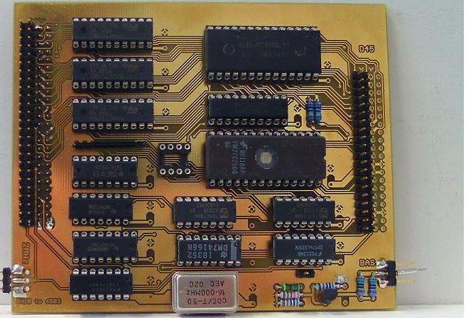
Contains a video RAM, a character generator ROM,
a shift register, an analog video output...
and a clock generator.
Said clock generator has to drive the CPU with 2 MHz.
One line of text is supposed to have 80 characters.
Because I ran out of 100 nF capacitors in "standard package",
I soldered 100 nF SMD capacitors at the bottom of the PCB.
A DIP switch was supposed to be plugged into that 8 pin IC socket.
Unfortunately, when plugging that switch into the socket,
there will be mechanical problems when plugging D45 and X45 together...
so I just soldered 4 pins of that socket to GND, and then to be done with.
X45 backplane:
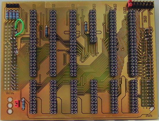
Ignore that green piece of wire...
Jumper\switch in the lower left area is for enabling the blinkenlights.
The jumpers in the upper left area are for the output enable
for the 74573 latches which emit raster and video address.
When using X45 together with D45, leave them OPEN.
The jumpers in the upper right area handle the chip select signals.
Note that piece of Tesa (TM) in the upper middle area,
for preventing short circuits between traces at the bottom of the X45 PCB
and the metal can oscillator at the top of the D45 PCB...
C45 control module
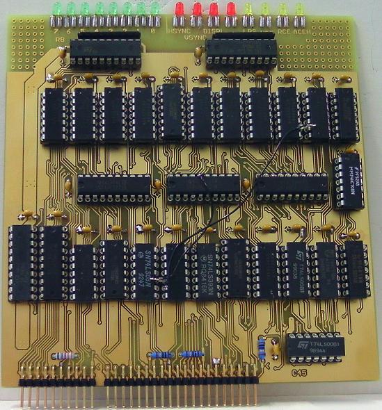
That's the place where the control signals for all those counters
and the status output signals from all those comparators are going to meet.
Schematics still are a bit messy,
contain a few little errors,
and are not optimized for speed.
Don't mind those wires, I think I already fixed this
in the schematics and in the PCB layout.
T45 horizontal\vertical timing module
Horizontal\vertical related registers, counters, comparators etc.
R45 raster timing module
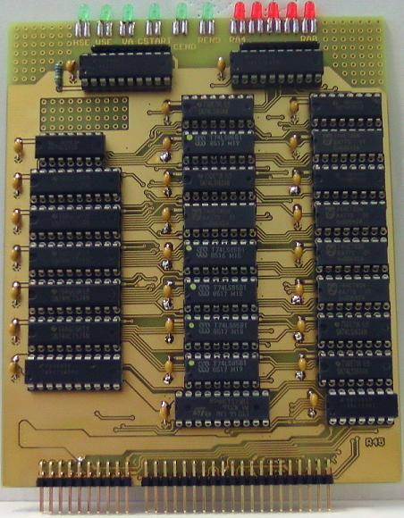
Raster timing and cursor.
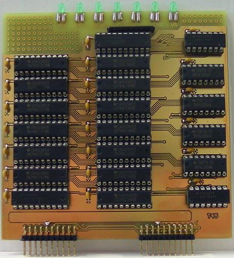
G45 8 Bit video address generator module
Two PCBs required,
two PCBs shown in the picture:
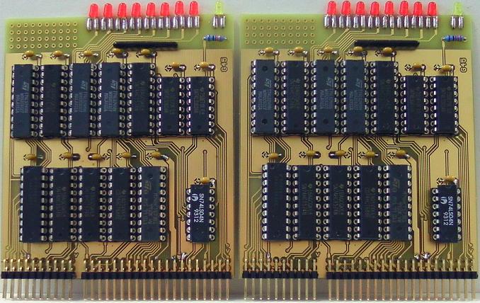
Doing a layout for one 16 Bit module turned out
to be a little bit too difficult,
so I had to split that part into two modules 8 Bit each.
(c) Dieter Mueller 2015