
An experimental attempt of building something like a 6532
with 74XX TTL chips.
The design might have some issues,
try reading the schematics at your own risk...
you better check, if the circuitry which detects timer overflow
works as intended...
and the prescaler isn't set to :1 by the timer interrupt.
I\O and bus connectors are supposed to be compatible
to Daryl Rictor's SBC-2...
but X32 also has a bus connector that is supposed to fit
to the Elektor Junior Computer.

Test setup:
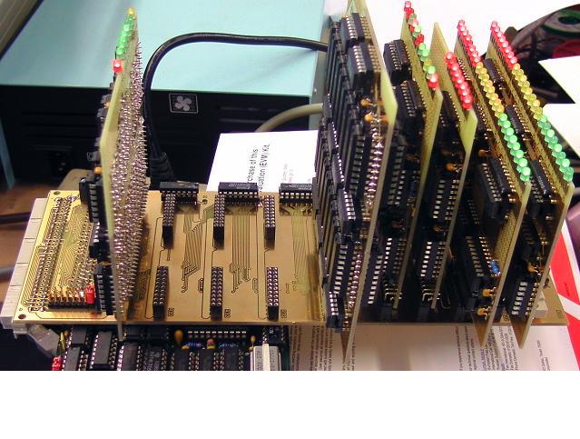
Bottom: my DRC2 SBC, which is supposed to be compatible to the SBC-2.
X32 backplane is plugged into DRC2.
Plugged into the X32 backplane, we are supposed to have:
1* 1PA22, Port A module
1* 1PB22, Port B module
1* T32, timer module
1* I32, timer control and interrupt module
4* R32, 4* 32 Bytes of RAM that is... (only 1 module was built)
1* B32, bus interface
X32 backplane:
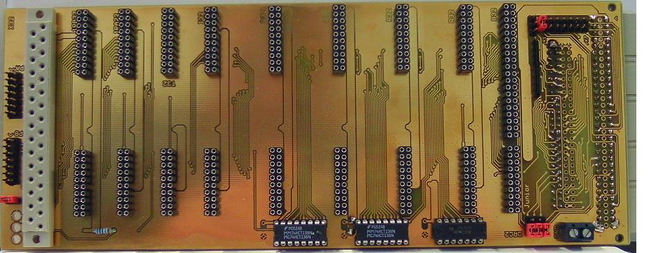
Jumper\switch in the lower left area is for enabling the blinkenlights.
The jumpers in the right upper area are for handling chip select signals,
and for connecting the interrupt output either to NMI or IRQ.
The jumpers in the right lower area are for selecting
if X32 works with a DRC2, or with the Elektor Junior Computer.
Please consult the X32 schematics,
to see which jumper does what,
and how the X32 shows up in the DRC2 memory map.
Warning:
That 31 pin female connector at the left was supposed
to resemble the Junior Computer I\O port pinout,
but something went wrong:
pinout is reversed.
I suggest to correct the package of the connector,
the schematics, the PCB layout...
or to solder the connector into the bottom of the PCB instead.
When making a redesign, maybe you should include a SRAM socket
into the backplane because not everybody might like soldering
a 128 Bytes SRAM from 74574 chips...
About that connector at the right for plugging X32
into the Junior computer:
Note, that like with the Junior Computer,
the connector is at the bottom of the PCB !
I only had a female 96 pin 90 deg connector in the drawer,
not a 64 pin connector as required...
that's why the layout shows a 96 in connector.
The row of pins in the middle of the connector is unused.
One more thing: be very careful when plugging X32
into a Junior Computer, because at the connector of said computer
we have -5V and +12 V present.
One little mistake there could be going to be quite expensive.
B32 bus interface
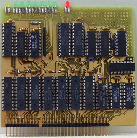
1PA22 Port A module

Port A has open collector outputs.
There is a pullup resistor network for the port lines
in the schematic and layout of the port lines.
I suggest to solder a single row precision socket into the PCB,
to make sure that you are able to try different resistor values,
or to go without pullup resistors if necessary.
1PB22 Port B module

Port B has three state outputs.
There is a pullup resistor network for the port lines
in the schematic and layout of the port lines.
I suggest to solder a single row precision socket into the PCB,
to make sure that you are able to try different resistor values,
or to go without pullup resistors if necessary.
BTW: Port A module and Port B module have identical pinouts.
T32 8 Bit timer module with prescaler
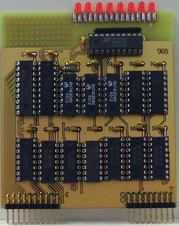
BTW: failed to buy synchronous down counters.
So I just took 74163 synchronous up counters
and inverted their inputs and outputs with 7404,
to make them up_counters look like down_counters
for the CPU...
I32 timer control and interrupt module
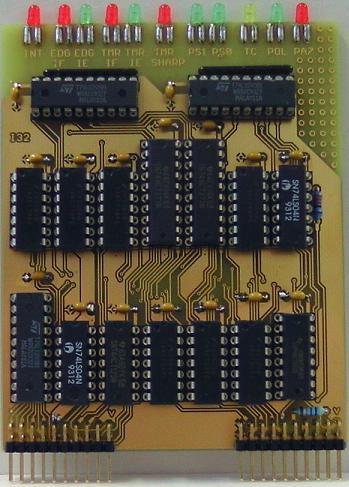
This module controls the timer, does edge detection,
and generates the interrupt.
R32, 32 Bytes of SRAM...
This PCB has ICs at both sides,
similar to the register section of my old TREX CPU project.
Top:
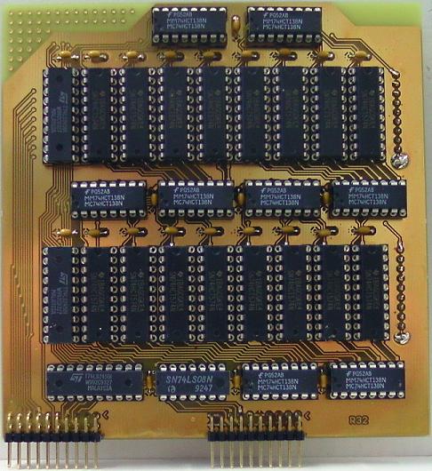
Bottom:

Soldering something like that sure isn't for beginners...
Don't worry about that pullup resistor,
I have already integrated it into the schematic and layout...
I think.
BTW: when buying a few hundred 74HCT574 at a big distributor,
price for them chips goes down pretty much.
Sure, it would have been possible to use a single SRAM chip instead.
But hey... that's your chance to build your own Atari 2600 from TTL chips.
(c) Dieter Mueller 2015