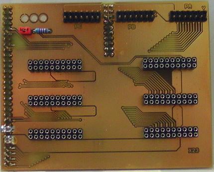
This isn't exactly a 6523,
because it has no 6523 bus interface.
I just used it as a "test adaptor"
for the 2B22 bus interface and the I\O port modules
from the X22 (6522) project.
I\O and bus connectors are supposed to be compatible
to Daryl Rictor's SBC-2.
X23 backplane:

Jumper\switch in the upper left area is for enabling the blinkenlights.
2B22 bus interface

The jumper field in the lower right area is for the chip select.
The bus interface is from the X22 project (6522),
what means that it decodes A0..A3.
Unlike the 6522, the 6523 doesn't have 16 registers,
so for better compatibility it's possible to deactivate
the unused address lines with the three jumpers
in the lower left area of the PCB.
1PA22 Port A module

Port A has open collector outputs.
There is a pullup resistor network for the port lines
in the schematic and layout of the port lines.
I suggest to solder a single row precision socket into the PCB,
to make sure that you are able to try different resistor values,
or to go without pullup resistors if necessary.
1PB22 Port B module

Port B has three state outputs.
There is a pullup resistor network for the port lines
in the schematic and layout of the port lines.
I suggest to solder a single row precision socket into the PCB,
to make sure that you are able to try different resistor values,
or to go without pullup resistors if necessary.
BTW: Port A module and Port B module have identical pinouts.
(c) Dieter Mueller 2015