Here is the evolution of my first SYM-1 from out of the factory box through several add-ons winding up with a dual floppy disk system and 32k RAM
Questions? email n5fee@netzero.net
The standard SYM shipped with 2k RAM and one 6522 VIA with the MON 1.1. The other items were sold as options and priced accordingly. Everything was expensive in 1978 so I ordered the minimum for $239 plus shipping. After reading all of the books and beginning write a few short programs (all had assembled and keyed in thru the onboard keypad) I ordered 3k more of RAM to fill up the board. Shortly after adding the ram I ordered a second 6522 to fill up the onboard I/O.
Shortly after learning a little about the board, I added the DB-25 connector and made up connections to allow me to use a RS232 terminal and an ASR 33 teletype I had a work (I was an engineer at Rockwell International). Having the teletype allowed paper tape to be punched for storing and loading programs without having to re-key the code each time. The teletype also provided for a printout. Remember the MX-80 (80 characters per second) printer was new then and cost several hundred dollars (minimum wage was about $3.00/hr). and was out of the reach of individuals. Dumb RS232 terminals were also several hundred dollars and usually only available at industries.
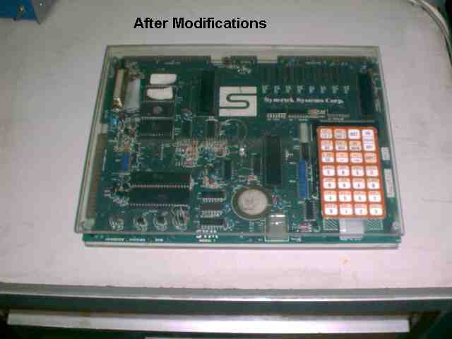
I could see the SYM keyboard was not too strong, so I mounted the keypad on a piece of 1/4 inch thick Plexiglas. I sandwiched the SYM in-between two pieces of Plexiglas with the keyboard and DB25 connector mounted to the Plexiglas for mechanical strength.
The following two photos show the setup.
After several months I began to write longer programs and needed more memory so my next addition was a 4k expansion memory board. This board plugged into the buss connector and used 2114 RAM's just like the SYM used. Sometime after adding the 4k (eight chips) I piggybacked eight more on top of the first row to give a total of 8k memory expansion. Here is a photo of the 8k expansion module. Notice each chip has one on its back will all pins parallel except the chip select pin which is slightly bent out and has a separate wire wrapped on it. By doing this same trick on the main board, you could have 8k on the main board. I did this as well, so 8k on the main board and 8k on this expansion gave you 16k, a huge amount of memory.
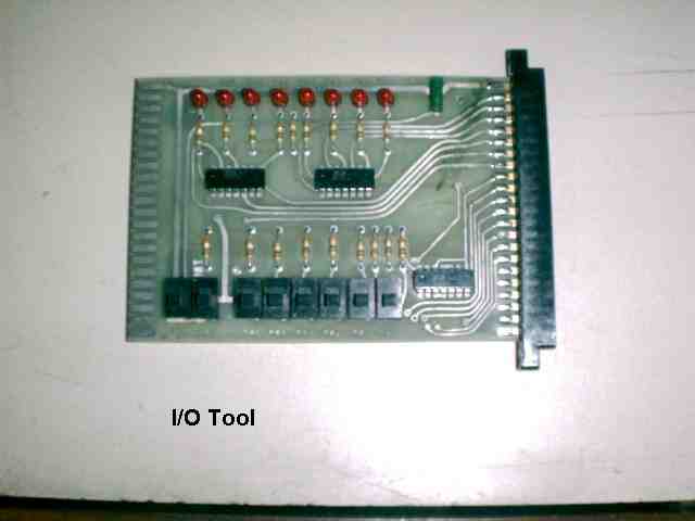
While learning to do I/O, I got tired of getting the voltmeter out and trying to see which pins had changed state. I designed and built this board that monitored the logic status of one VIA and would light up the LED's to show the status of each line. I made this one to go on the A connector, so I made a place to plug in my teletype on one side (left side below) and my RS232 terminal on the other side. I also made connections for my tape recorder which was used to store programs on. This is a feed thru device and world allow the VIA signal to be monitored while it was controlling something else.
Several years later, I bought another SYM that came with this board which is similar to the one I just described. It allows one half of a PIA to be monitored as an output and provides switches to be used as inputs.
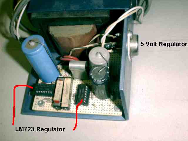
This is the power supply I built up to power the SYM. It is just a full wave bridge with a 7805 single terminal regulator for the 5volts. I later added two LM723 low current regulators to provide 27 volts for burning 2708 EPROM's and later 25 volts to be used while burning later model EPROMs.
Here is the First EPROM programmer I made. It was for 2708 chips. It plugged into the AA connector.

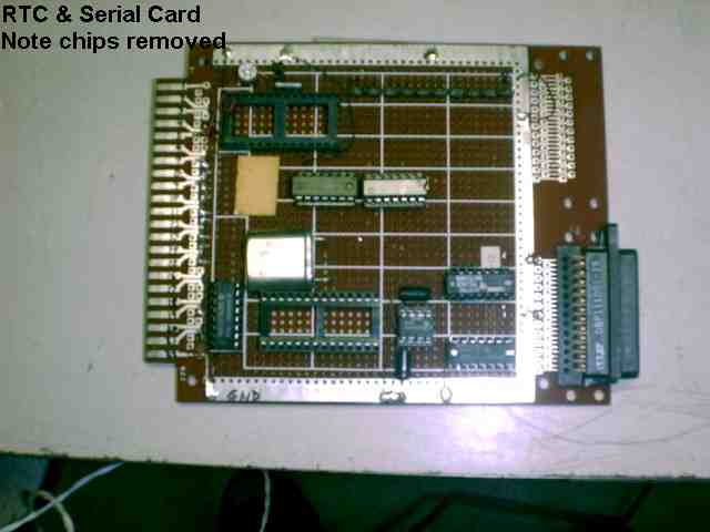
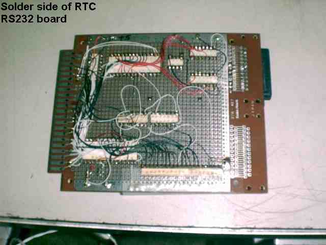
About this time I needed more serial I/O and was interested in having a real time clock so I made up the next addition. This board has an ICL7170 real time clock chip and a Rockwell Serial I/O chip. This gave me the extra RS232 port to print program listings on a newly acquired Epson MX-80 printer which the company bought. I could use the RTC to time and date stamp the printouts. This add-on board was plugged into a small back plane of several 44 pin edge connectors that I salvaged from some junk equipment. I just plugged them in and let the board lay on top of the Plexiglas cover I had added earlier.
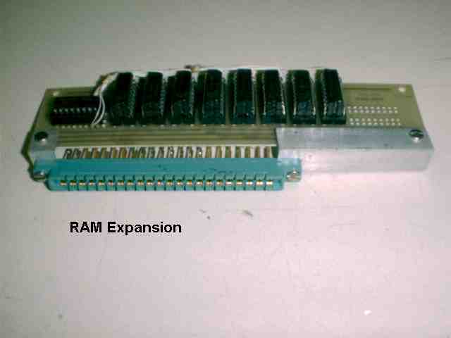
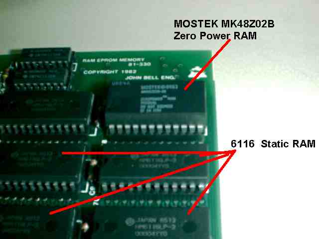
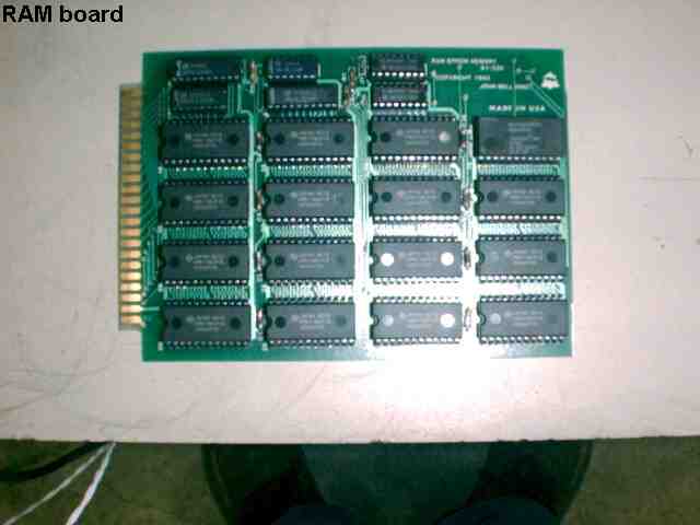
I then bought another SYM that had the RAE chips so now I could quit hand assembling my programs and use a real assembler. But I soon discovered I needed more memory. So I bought a commercial 32k memory board from John Bell Company. This board would take 2k chips either RAM or EPROM and was a Cadillac in its time. I used the brand new 2k Battery backed up ram chip from MOSTEK in one of the sockets, so I could load my printer and RTC drivers in high RAM and leave them there without having to re-load them every time. It worked great. Here is the RAM board.
By this time several people were working on Disk Operating Systems for the SYM. I bought one of the least expensive systems that used a Commodore 1541 disk drive. Using a very simple interface and an off of the shelf VIC-20 disk drive with the DOS software gave me a simple DOS that would let me retire the old cassette tape deck.
I used this DOS for several months while I built up an interface to use a DOS that I had gotten from a member of the SYM-Physis group who lived in Hong Kong. He had written a very robust DOS that worked thru a standard FDC chip at the time. The WD1793 single chip disk controller was being used by a lot of the early disk drives and I wanted to have a disk system based on the industry standard disk format. I obtained a spare disk controller from a Radio Shack TRS-80. After studying the drawings I made several dozen changes to the TRS 80 board and made it work with the DOS from Hong Kong. This is a very good DOS and I later made up a new interface circuit from scratch using the WD 2793 interface chip. This later system is shown on another area of my web site.
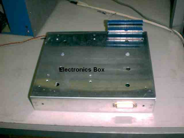
Here is the Disk System using the TRS 80 controller.
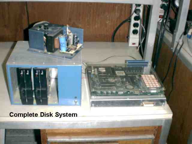
The electronics was housed in an aluminum chassis below the SYM. The Back plane carried the signals from the SYM into the box below. The SYM was attached to the box by three small 4-40 screws threaded into the Plexiglas from inside the box.
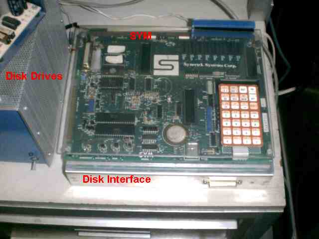
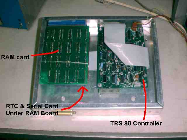
The modified TRS 80 controller card is shown on the right side below. The left side has two cards stacked on top of each other, each plugged into the back plane buss. The top card shown is the 32k RAM card. Below this RAM card is the card with the RS233 chip and RTC described above. The buss signals were ran from this card thru the ribbon cable to the TRS 80 controller card shown below. The disk drives themselves were plugged onto the TRS 80 card using an edge connector (not shown in this photo) exiting the top right corner of this photo.
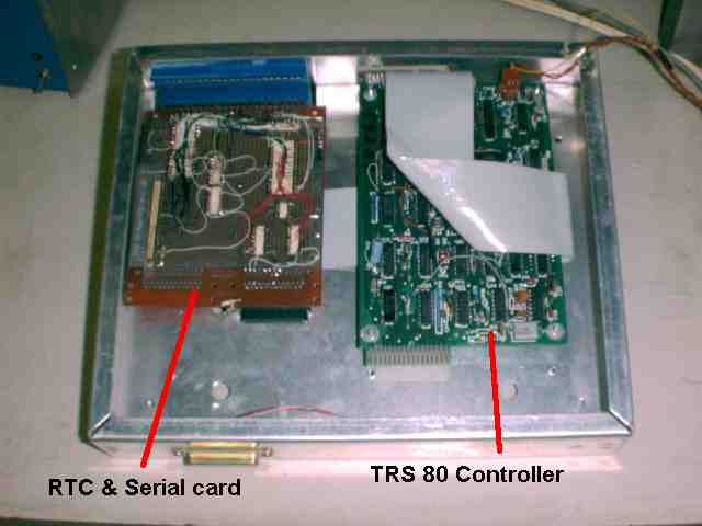
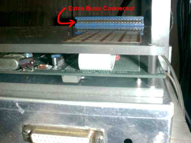
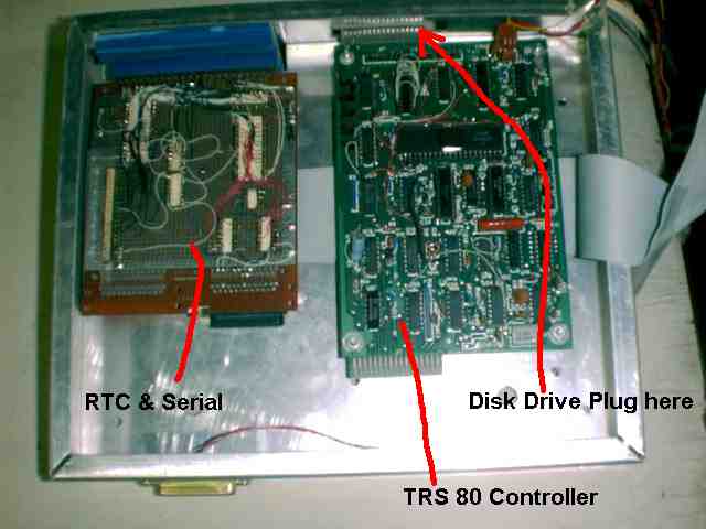
Here you can see the edge connector that the disk drive box plugs into. The RAM board has been removed to show the RS232 and RTC board on the left plugged into the back plane buss.
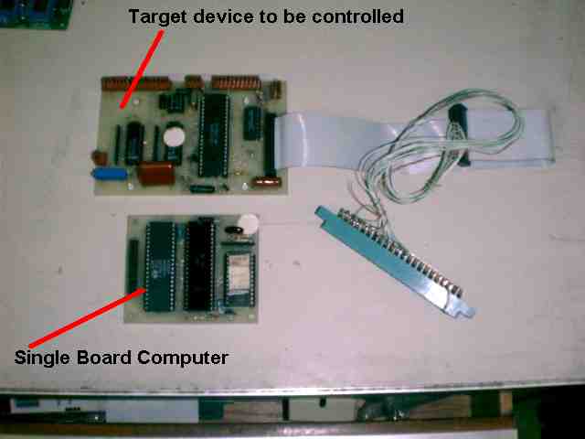
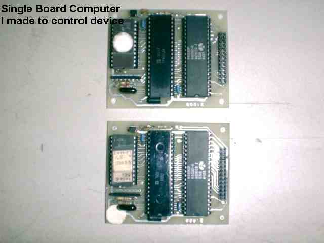
Shown below is a couple of small single board computers I made up to use in some custom equipment I designed. These small boards have a 6502, 6532 and a 2732 Eprom. This makes a complete computer with two eight bit ports. Power comes in, and the port signals go out the header connector on the right hand side.
Here is another board with a 12 bit A-D and some other I/O that is controlled by the single board computer above. In actual use, the computer board would connect to the larger board by the ribbon cable. Here is shown an adapter cable that plugs into the SYM. Using this scheme, the programs are written and debugged while under control of the SYM. When everything is working correctly, the code is re-assembled using the VIA address of the small single board computer above, and burned into an EPROM. Now when the single board computer starts, it runs the program that has already been de-bugged on the SYM.