|
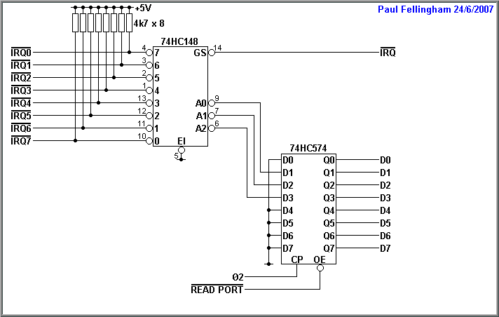
Note - the IRQ line numbers don't match the 74HC148 input numbers. This is because the 74HC148 has active low outputs. With the circuit as shown, the value read by the processor is the number of the IRQ line multiplied by 2.
When any of the 8 interrupt lines is pulled low, the 74HC148 priority encoder pulls its GS pin low. This is connected to the CPU's IRQ line and causes an interrupt.
The interrupt inputs are prioritised, with IRQ0 having the highest priority and IRQ7 having the lowest priority.
It might seem that the latch is unnecessary and a 3-state buffer could be used instead. However, interrupts are not synchronous to the CPU clock. If the interrupt lines changed just as phase-2 went low when the CPU was reading the IRQ port, the CPU could read garbled data and jump to the wrong address. By latching the IRQ value when phase-2 goes high, we guarantee the data will be valid when the CPU reads it.
After pushing registers onto the stack, the processor reads the input port. This gives the number of the highest priority IRQ line that is currently active. The CPU can then use this number to identify the interrupting device. Suitable code for the 65C02 and 65C816 (with 8-bit index) is as follows
IRQ PHX
LDX IRQPORT
JMP (IRQTABLE,X)
IQRTABLE Address of service routine for IRQ0
Address of service routine for IRQ1
Address of service routine for IRQ2
...
This pushes X onto the stack, then loads the value from the IRQ port into X. This is then used, with indexed indirect addressing, to jump to the start of the appropriate interrupt service routine via a jump table.
With the NMOS 6502, which does not have the preindexed indirect JMP instruction, the following code is required.
IRQ PHA
TXA
PHA
LDX IRQPORT
LDA IRQTABLE,X
STA TEMP
INX
LDA IRQTABLE,X
STA TEMP+1
JMP (TEMP)
IQRTABLE Address of service routine for IRQ0
Address of service routine for IRQ1
Address of service routine for IRQ2
...
This copies the interrupt handler address from the table to a temporary location, then jumps indirectly via this location.
Note that the IRQ port inputs the active IRQ on D1..D3 rather than D0..D2. This automatically multiples the IRQ value by 2 to match the spacing of the jump table.
After an interrupt service routine has finished and executes RTI, if a lower priority interrupt is still active, the processor will be interrupted again. This time, reading the IRQ port will see the lower priority interrupt and the processor will
service the second device.
Note - In order for lower priority interrupts to be seen when two devices interrupt simultaneously, this circuit requires a level sensitive interrupt input on the processor. As a result, it can be used with IRQ on the 65C02 and 65C816 but not with NMI, which is edge-sensitive.
|
|

